UPDI – Unified Program and Debug Interface – is the new programming and debugging interface on new ATtiny MCUs from Microchip. The UPDI requires just a single pin on the MCU, so it is very suitable for low-pin count chips. Physically it is implemented as a bidirectional (half-duplex) UART protocol. UPDI pin is typically located with the RESET pin on the ATtiny MCUs. A programmable fuse in the MCU switches the RESET/UPDI between these three modes:
- UPDI programming interface – factory default. Pin always behaves as the UPDI interface. In this mode the MCU could be programmed using many cheap programmers, e.g. one possibility is mentioned here.
- /RESET – the pin behaves as a RESET pin (active low). Programming the MCU when the pin UPDI pin has been switched into the RESET mode requires first applying a 12V pulse followed by a special KEY word. As of this writing in August 2019 only the ATMEL POWER DEBUGGER (not cheap – 169 EUR) is capable of generating the 12V UPDI activation sequence. I don’t posses this debugger.
- GPIO mode – the pin could be used as another GPIO pin. A 12V activation pulse is required to start the UPDI communication as in the case of RESET mode.
UPDI Activation
In a normal MCU working mode, when there is no debugger connected, the internal UPDI interface is in a power-down state and it consumes basically no power. This is very important feature for any low-power applications of the MCU.
In the idle state the UPDI pin is pulled high by a built-in resistor. When a debugger/programmer is connected, it will pull the UPDI pin down for a moment, thus activating the UPDI interface. Then the UPDI protocol could start. This process is shown in datasheet picture below:
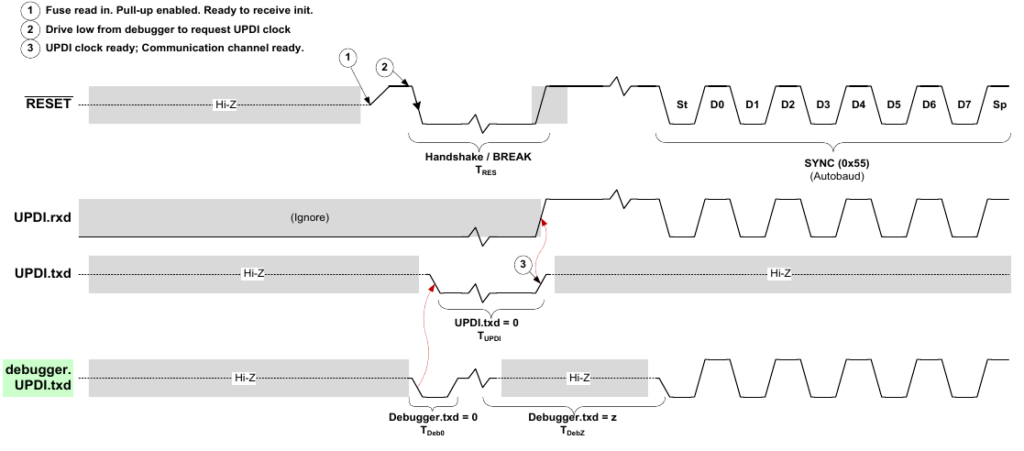
After UPDI activation low-pulse, the SYNCH character 0x55 must be sent from the debugger within 14ms. If not, the interface is supposed to de-activate itself.
The Problem
It was discovered, by analysing a problem situation, that the UPDI interface in ATtiny will not deactivate itself when it gets activated by a random electrical noise on the UPDI pin:
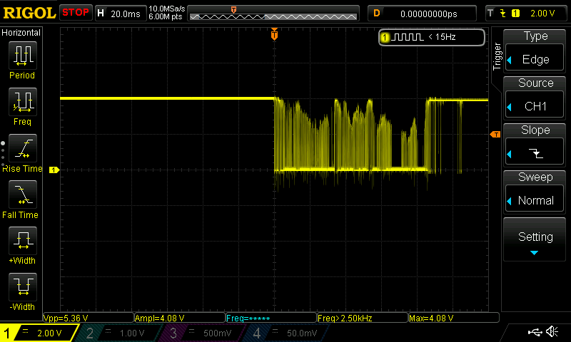
This kind of electrical noise comes for example from the programming connector, when attaching or dettaching the connector while the target is under power.
Why this is a problem? Since active UPDI draws cca 2mA of current from VDD, it will quickly drain battery in any low-power application.
Mitigation
- In typical use-cases the ATtiny target is powered down after software is programmed, this clears UPDI, and after the next start there is no problem!
- In case you need to disconnect the programmer cable from the target while the target is running, do it while the programmer is still powered up.
- Perhaps the best mitigation would be to switch the UPDI pin into the reset mode, and use the 12V-capable programmer. At the moment I don’t the programmer capable of this mode, so I cannot test it.
I have seen this issue. Struggling with it right now.
Any pulses on the UPDI can activate the interface in deep sleep mode, draining batteries. Did you ever come across a solution /work around?
Hello, the only good solution I know is to switch UPDI into the 12V programming mode. This requires a programmer supporting this mode. With 12V mode the UPDI pin should be robust against random pulses, they say. But I did not test it, I don’t have a 12V-capable programmer!
A simple workaround (if the 12V mode cannot be used) could be to put a large capacitor (eg. 2u2) with a series jumper on the UPDI line. The capacitor prevents noise spikes, but you must manually disconnect the cap before programming (hence a jumper).
— Jarda
xrn50v