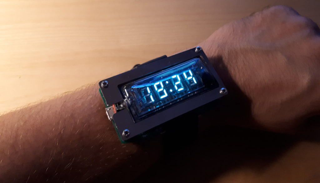
The “EVERGLOW“ Watch is a vacuum tube clock put on the wrist:
Features:
- Soviet VFD tube IVL2-7/5
- Time (24h), Date, (dd-mm-yyyy), day of week (Mo-Tu-We-etc).
- Alarm clock (7-day) with a beeper.
- Stop-watch (00:00 => 9:59:59)
- Count-down clock (99:59 => 00:00)
- 50mAh LiPo accumulator (lasts 1-2 weeks), charging over a Micro-USB -port.
- Two buttons for activation and settings.
- Dimensions 70 x 41.5 x 11mm
- Open hardware, open source.
- // DESIGNED IN CZECHIA //
- // HACKABLE SOFTWARE INSIDE //
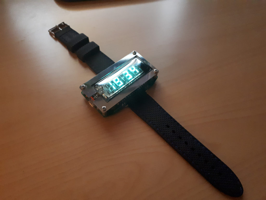
Photo Galery
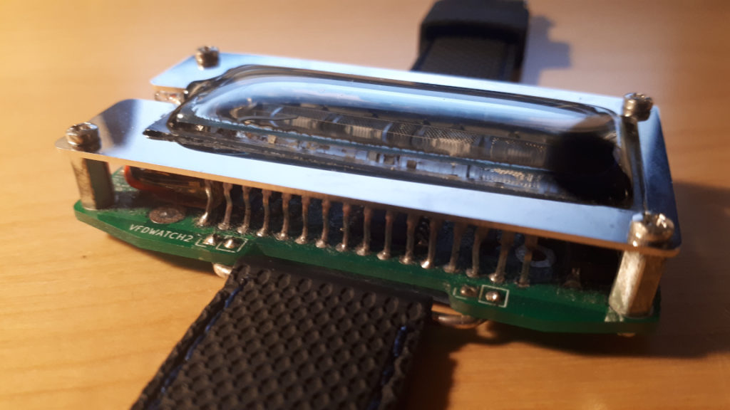
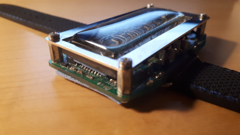

Two buttons in the upper part 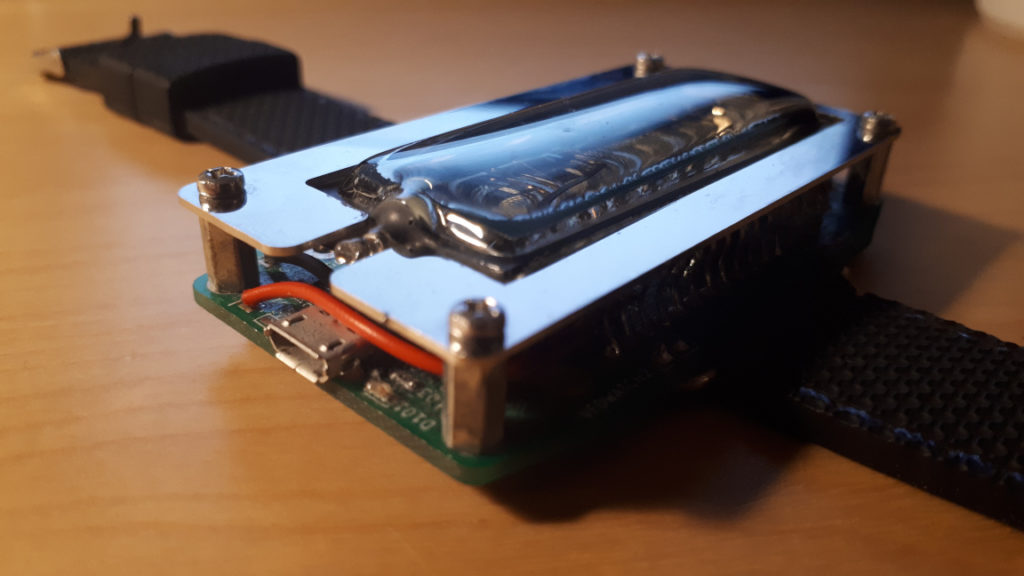
Micro-USB for charging the battery 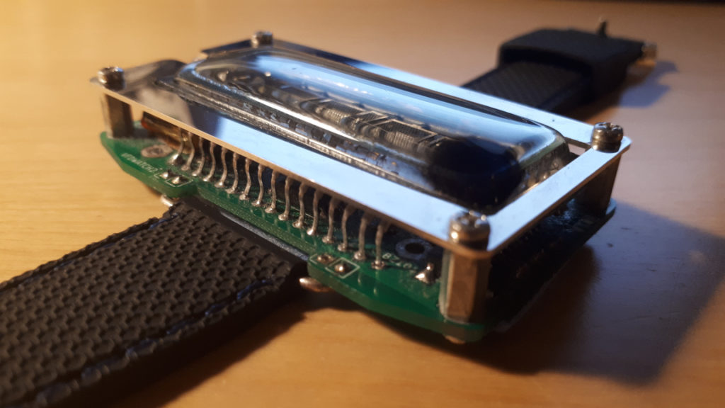

Padding with space-foam at the bottom 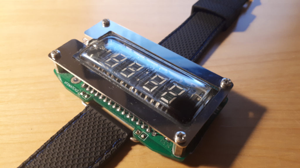
Functions
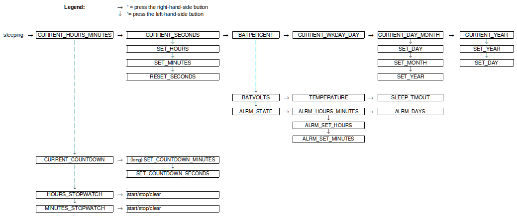
The watch has two buttons at the upper side – they are visible in one of the photos above. In the idle state the display is off and it must be activated by pressing a button. After 5 seconds of no user activity the display powers down automatically.
User control: Start by pressing the right-hand-side button (R-BTN); the display powers up and starts showing the current time (hours:seconds; state named CURRENT_HOURS_MINUTES). Press R-BTN again to show the current seconds, then battery remaining charge in %, then the current week-day, then the current date (day.month), and finally the year. Or press L-BTN to show the countdown timer, then the stop-watch.
To adjust the current time, press the R-BTN twice so that the current second is showing (e.g. ” :20″), then press and hold the L-BTN for 2 seconds until the watch beeps and enters the setting mode. It is now possible to set the current hour – the watch is showing e.g. “08:35” and the digits “08” are blinking. Pressing R-BTN adjusts the value up by 1, pressing the L-BTN cycles through setting of hours – minutes – seconds. Hold L-BTN for 2 secs to exit the setting mode.
Here is a complete state diagram of the “screens”. The idle state (display off) is marked “sleeping”. Arrows pointing to the right (–>) mean pressing the right-button, and arrows pointing down mean pressing the left-button.
To the sides of the two buttons there are two green LEDs. They are flashing during alarms and also during error situations (low battery). There is also a built-in buzzer for beeping.
Battery should be charged via the USB when the BATPERCENT screen shows bellow ~30% of remaining charge, or immediately when both green LEDs D104, D105 are flashing after wakeup instead of the VFD lighting up (batt voltage <3.3V). When charging complets the red LED D101 shuts off. Charging takes about 1 hour.
VFD Tube
“Vacuum Fluorescent Display” (VFD) is true vacuum tube technology. Technically a VFD is a direct-heated triode. There are three basic elements in the vacuum tube: filament, grids, and anodes – see this picture:
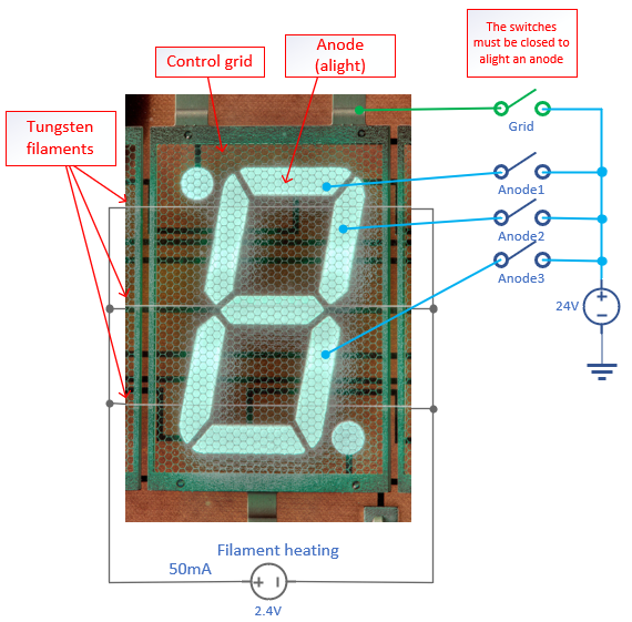
Filament is shared across all digits of the tube. In case of IVL2-7/5, used in the EVERGLOW watch, the filament is heated with 2.4V / 50mA. The relatively large power (120mW) needed for the heating is the main reason why the tube cannot be illuminated all the time: the battery would drain quickly.
Control grids are common for all segments of one digit or character. IVL2-7/5 can display 5 characters: “88:88” – i.e. four 7-segment digits and the 2-segment double-dot in the middle – and therefore it has five grids G1 – G5.
Anodes form individual segments of the display. They are covered with a green phosphor that lights up when it is bombarded by free electrons emitted from the hot filament. This is the same process as in a CRT. A segment is iluminated when a high voltage +24V in case of IVL2-7/5 – is applied both to the anode and to the control grid in front of it. The VFD is naturally operated in a multiplexing mode: corresponding segments in different digits are electrically connected in a single anode. The segments are illuminated depending which grid is activated together with the anode.
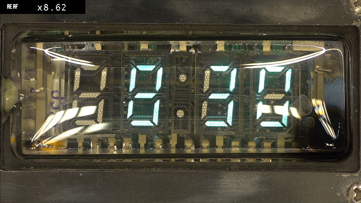
In the photo below the structure of the IVL2-7/5 display is well visible: three horizontal filament wires, five control grids in front of each digit, and anode segments. Click the image to see a bigger picture with all details.
The VFD IVL2-7/5 comes packaged in a paper wrap:
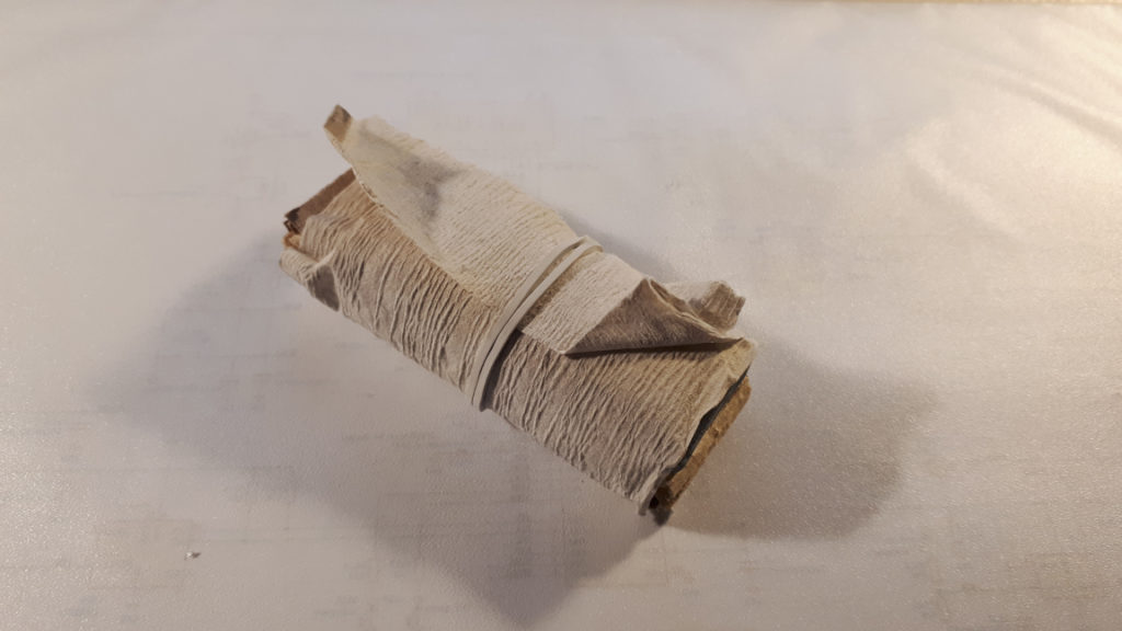
Each tube is packed in a paper wrap 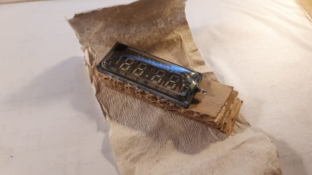
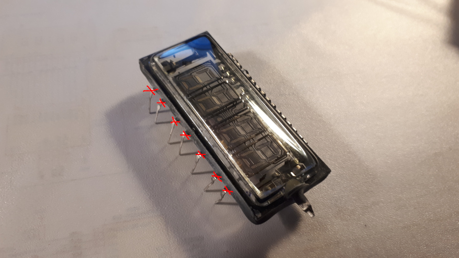
Note: marked pins should be cut away for easier assembly of the watch 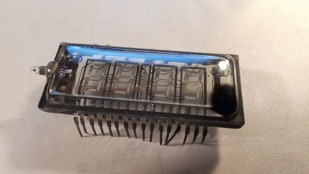
The black spot lower-right is called “getter”
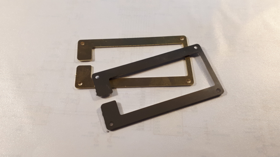
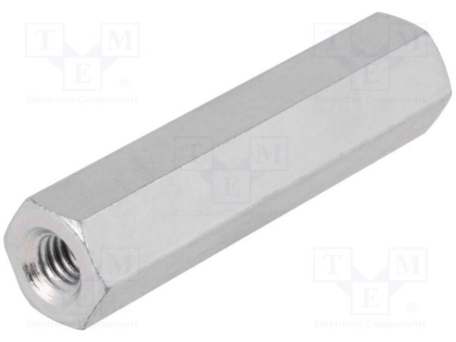
On IVL2-7/5 cut away all the 7 pins on the upper part. They are marked with red crosses in one of the pictures above. The VFD is sandwiched between the top metal plate and the PCB. The top plate is held to the bottom by four metal spacer (M2x8mm) and eight M2 screws.
The black spot visible at the lower-right corner of the display is not a fault. Quite contrary, it is the getter material which is necessary during manufacturing to achieve the high vacuum in a tube. Should the tube broke and an air leak in the getter becomes white.
Construction
Schematic diagram & BOM
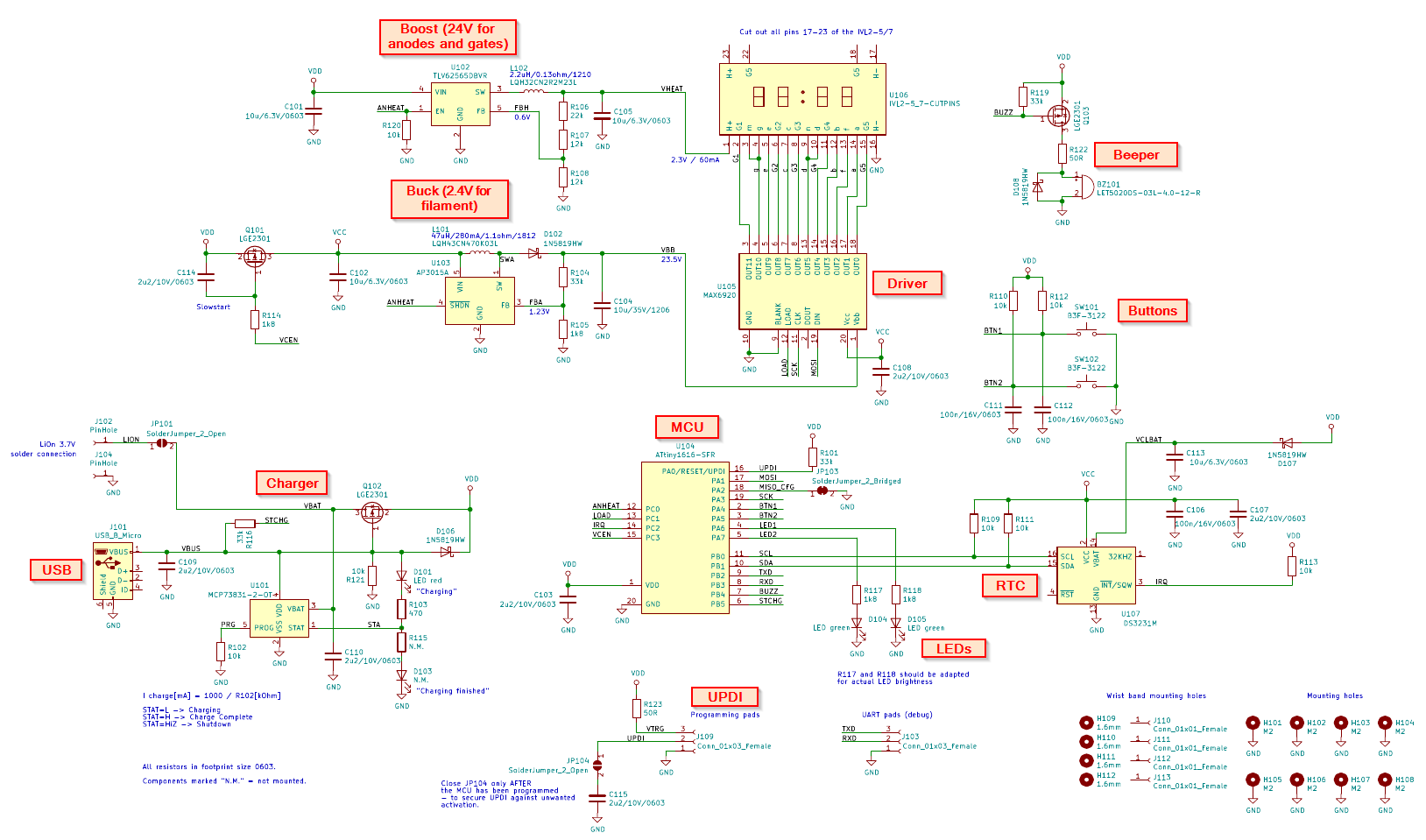
Display Circuit
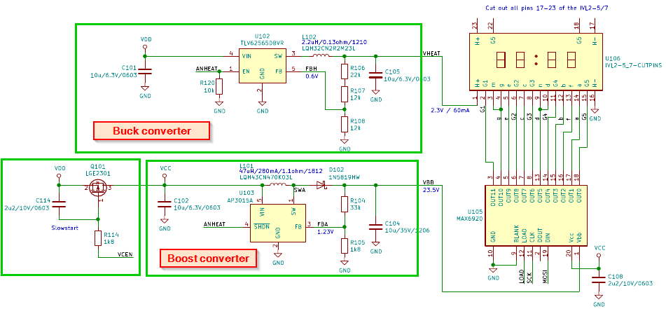
Filament voltage +2.4V for the VFD display is generated in a step-down buck converter TLV62256DBVR. The converter works from the VDD voltage which varies between +3.3V (low battery) to +5.5V (when the USB charging is active). Filament requires current around 60mA, therefore it makes sense to use a converter instead of a linear regulator, to save power.
Anode and gate voltage +24V for the display is generated in a step-up boost converter AP3015A. Current draw from the +24V to anodes/gates is less than 1mA. Transistor Q101 completely shuts off the voltage VCC to the converter when it is disabled. It is necessary because the VFD driver MAX6920 draws some hundrends of uA even in an idle state.
The VFD driver MAX6920 is a 12-channel high-side switch with an SPI interface (a shift register). MAX6920 is powered from VCC, which can be shut off by Q101, to save power when the watch is idle.
Processor Circuit
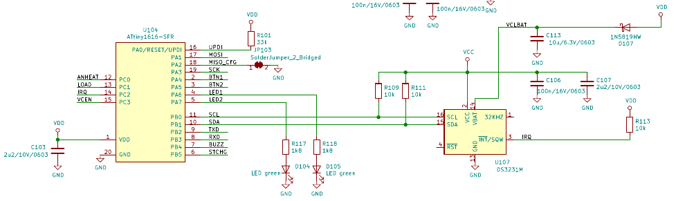
The main processor is ATtiny1616-SFR. It is an 8-bit MCU in SOIC-20 package, with 16kB of flash and 2kB of RAM. It has an internal 20MHz oscillator and can be powered directly from 1.8V to 5.5V. Therefore no LDO is necessary in this circuit. When the watch is idle the MCU is in a deep sleep, consuming less than 1uA.
Time & date is kept up-to-date not in the MCU, but in a dedicated RTC (real-time clock) chip – DS3231M. This RTC has an integrated temperature-compensated oscilllator (TCXO) and an I2C interface for communication with the MCU. Thanks to the TCXO the DS3231M achieves +-2ppm (+-0.172s per day).
Accumulator and the charger
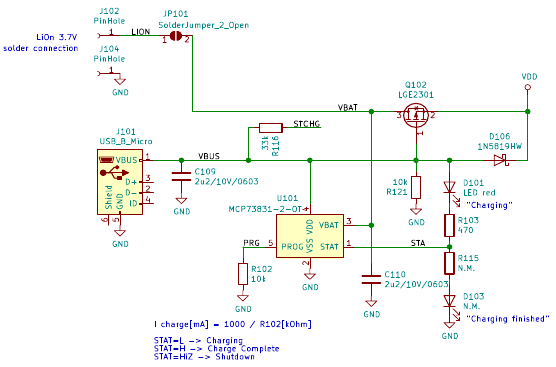
The accumulator is a 50mAh LiPo cell CELLEVIA BATTERIES L301020. Connections are soldered directly to the PCB.
Charging of the accumulator is realized by MCP73831-2. This chip signals charging by driving the STAT pin low, therefore iluminating the red LED D101. Transistor Q102 disconnects the accumulator from VDD when the USB power is available. It ensures that all charging current is directed to the accumulator only.
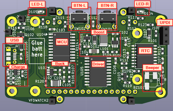
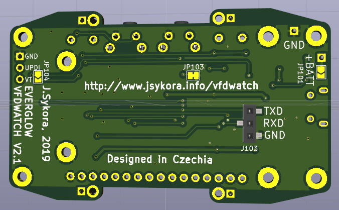
PCB
2-layer PCB with dimensions: 70×41.5mm, proven at allpcb.com (with the default manufacturing settings…). All components are assembled on the top side. Pin-headers shown in the 3D renders bellow should not be assembled.
Mechanical construction
Metal top-plate is made from 0.8mm polished steel with a laser-cut pattern according to this 2D DXF file:
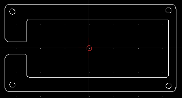
Many companies offer laser-cutting at a low cost; only the DXF file and the specification of material is necessary.
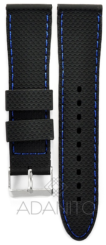
A wrist strap for a watch is connected to the main PCB very simply with a piece of 1mm thick wire which is threaded through the existing opening for an axis in the strap, and soldered to the PCB. The strap should be about 22mm wide. Suitable type is e.g. DILOY SBR22.1.5.22.
Firmware
Firmware for ATtiny1616 is written in C and compiled in Atmel Studio 7. It can be flashed into the ATtiny using for example the Pickit 4 or the cheap programmer made of Attiny817-Xplain Mini board.
The time and date information is kept up-to-date in the external clock RTC DS3231M. Most of the time the MCU ATtiny1616 is in power-down sleep state, waiting for an external pin interrupt: a button press, a DS3231 IRQ (in case the alarm is set), or a USB plug-in event. Upon wake-up the MCU enables the buck and boost converters to light up the VFD, then periodically refreshes the 7-segment 5-position display. Segments are multiplexed at a fixed frequency 500Hz running in a timer IRQ, from a 5-character display buffer. Foreground task handles I2C communication with DS3231M and updates the display character buffer according to the current displayed “screen”. Pressing a button changes firmware state to the next “screen”; all available screens are listed in enum Screens_t, and handled in a giant switch (cur_screen) { } in the main.c in a finite state machine.
i am just doing the copy of it.
Maybe the next version can have an atmega controller and a beitian BS185GPS for automatic timesetting…
Dear, this is a cool project! Are you willing to sell the watch? If yes, how much will it cost including shipping to Holland?
Thank you for yout time. With kind regards, Yil
Hi! Thank you for your interest! But sadly at the moment I am not able to sell the watch as a product. Too much work on other projects (mainly the kids 🙂 I hope to do it in the future, perhaps selling kits with the custom parts..
can i know if you order from jlcpcb? if yes whats is the cpl file?
Hi, I did not order at jlcpcb, and I don’t have the file!
send a mail to wolfhenk at wolfhenk dot de. i have jlcpcb files and one board is here what i can give to you
Hey, could you send the files?
vps0sb