New AVR processors from Microchip/Atmel use a 1-wire UPDI interface for flash programming. You could use either AVR ICE or Pickit 4 as the “official” programmers (I did not test any of them). Both of these cost >50 EUR.
A good alternative, presented in this post, is to modify the ATtiny817 Xplained Mini board (costs ~10 EUR) and use it as the UPDI programmer:

ATtiny817 Xplained Mini is the official evaluation board for ATtiny817 processor. Besides the ATtiny817 processor, the board also has another MCU ATMEGA3204 acting as a USB-powered flash programmer. By connecting this board to a PC, you get a complete working platform with an UPDI programmer in ATMEGA, and the user-programmable ATtiny817.
Modification: remove the 0-ohm resistor R203 near the ATMEGA. It is marked UPDI disconnect in this picture:

I add two single-pin headers: first connected to the output of UPDI on ATMEGA, second to the input of UPDI on ATtiny. Using a jumper wire between these two the system works as usual. Or the UPDI output could be brought to another board for programming of a different target.


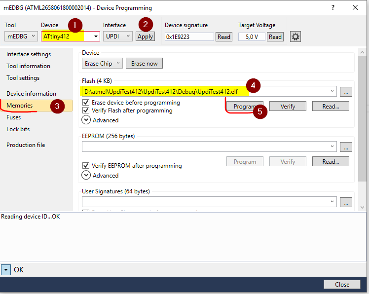
As the programming sw I use Atmel Studio 7. To program a different target than the default ATtiny817, you need to manualy write the device type in the Device drop-down list of the Device Programming window. Here I use it to program ATtiny402 on a breadboard:


Enjoy!
Hello Jarda, Great post! But the Studio 7 is always using simulation, only. I can see the device in the mEDBG window (as you posted), including reading fuses, memory, etc, but when I close the window and try to program it the Atmel Studio goes to simulation and the mEDBG is not present in the tool’s list. Is there something else to configure?
Hello Augusto,
Unfortunately, with this programmer hack, the Start button in Atmel Studio does not work. You must program the chip via the “Device Programming” window, section Memories, the button Program in the Flash section. I have added a screenshot of this step.
Consequently, debugging via Atmel Studio will not work; you have to debug your program the “hard way” with the help of UART, LEDs, etc.
Thank you, Jara, for the fast response to my help scream. After digging at AVRFREAKS I found another solution (at least to my case). I will left it here so other users may find it, as well. In the Atmel Studio 7,go to Tools menu / Options / Tools / Tool settings. Then set to FALSE the “Hide unsupported devices” variable. It did made the AtTiny1634 show up in the mDEBG option as debugger/programmer, allowing most of the debugging operations to work.
Hi,Jarda.Here’s the one who comes from the east of the world. I try to follow the steps you wrote on this website and wish promgramming to Attiny817. When I removed R203 and welded a jumping wire between the output of UPDI on ATMEGA and the input of UPDI on ATtiny, found that it is impossible to program into the Attiny.I dont know where the problem is and want your help.Would you pls do me a fever? TKS.
Hi, What is the error message in software (screenshot)? Do I understand correctly you want to program some other ATtiny on some other board? Can you share a schematic of your connections?
Hi,Jarda.Thanks for your reply. Uploading pics in comment is not supported, so I can only describe this problem by words.
I use the totally same board(ATtiny817 Xplained Mini) as yours. All I want is to use the MCU ATMEGA3204 on this board to program another ATtiny817(not on this board).
First, removed R203(the 0 ohm resistance) and connected 2 pads with wire as you did that shows in the 3rd pic(the yellow line) you posted on this website. And I found that PA0 is also connected with this wire.
second, connected PA0 and another ATtiny817’s PA0, and this ATtiny817 which is not on this board is my target to program. 5V Vcc and the same GND(with this board) is supplied with this ATtiny817.
Third, Atmel Studio 7.0 was used to program,but it didn’t work. The Error Message is : Erasing device failed.
I’m pretty sure that this board is totally ok to grogram its own ATtiny817. I dont know if the target ATtiny needs some other connections with this board.
I’ll be very thankful if you can analyse this problem and told me how to fix it.
It’s ok to send me an e-mail if you don’t mind and think it is nessary.
My e-mail address is: zyfmessi2008@126.com.
TKS!
I like this website because so much utile stuff on here : D. Joana Gerhardt Echikson