Philips PM3310 Digital Storage Oscilloscope
I got myself an old Philips PM3310 Digital Storage Oscilloscope (DSO). The scope has a classic CRT screen, but otherwise it is a fully digital device. The scope has two channels. Analogue bandwidth of the input attenuator/amplifier is 60MHz, which is not bad at all. Sampling frequency in real-time mode, however, is only 50 Mega samples per second. Each sampling ‘run’ after a trigger stores 256 samples into a RAM. The sample RAM has capacity for 4 independent waveforms. The 50M sampling speed allows single-shot time base up to 500ns/div, and a recurrent time base up to 5ns/div (sampling of repetitive signals in equivalent time). The internal CPU switches between the modes as needed.
Bluetooth Module (Re-)Investigation
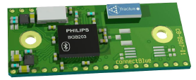
Some five years ago I bought a nice UART-over-Bluetooth adapter module. The module emulates a serial port (UART) over a Bluetooth connection. All necessary chips and an antenna are mounted on a small PCB board depicted below.
The type I’ve got is the cB-OEMSPA310i-04 with an internal antenna. The module requires only a 3.3V power.
Communication with the module is over serial UART at 3.3V logic levels. The basic RXD/TXD signal pair is complemented with hardware flow control via RTS/CTS, and an optional BT connection status via DSR/DTR. A three-colour LED (red, blue, green) can be directly connected to dedicated pins on the module to visually indicate the state of module to the user.
The BT module is controlled by standard AT commands. When powered up or after a reset the module is in a data mode with no connection over BT. Local application microcontroller connected to the RXD/TXD/RTS/CTS signals first sends an escape sequence, which normally consists of three forward slashes ‘///’. This puts the module into the AT mode. In AT mode the strings sent over the local UART are interpreted as commands, while in data mode all data is passed through to bluetooth and over the air.
Talking Clock: COMPLETED!
Finally I declare the Talking Clock project complete! Hardware is built and is working, documentation has been written.
The permanent project web page is here. I have also created a parallel page on hackaday.io. Enjoy!
Mailbag: ePaper Display Module
Look what I’ve got by post today from our Chinese comrades at ‘Good Display’ factory: a nice small 2.04-inch electrophoretic display (EPD), or better known as ePaper/eInk display or ’electronic paper’.
[caption id=“attachment_232” align=“alignnone” width=“856”]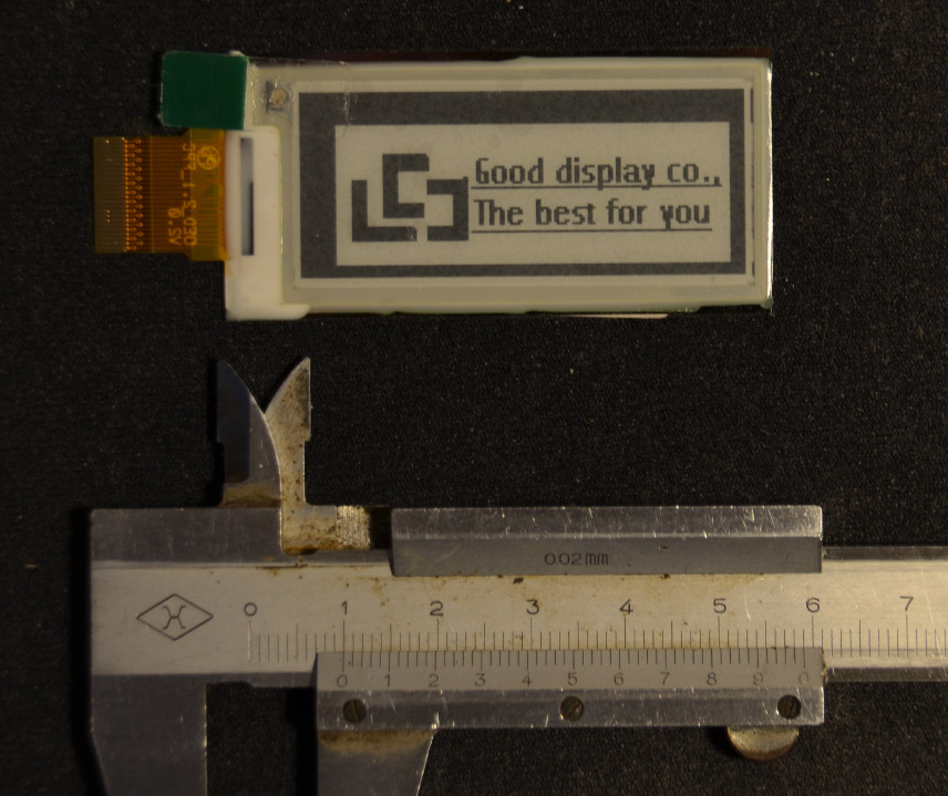 ePaper EPD display front side view[/caption]
[caption id=“attachment_231” align=“aligncenter” width=“632”]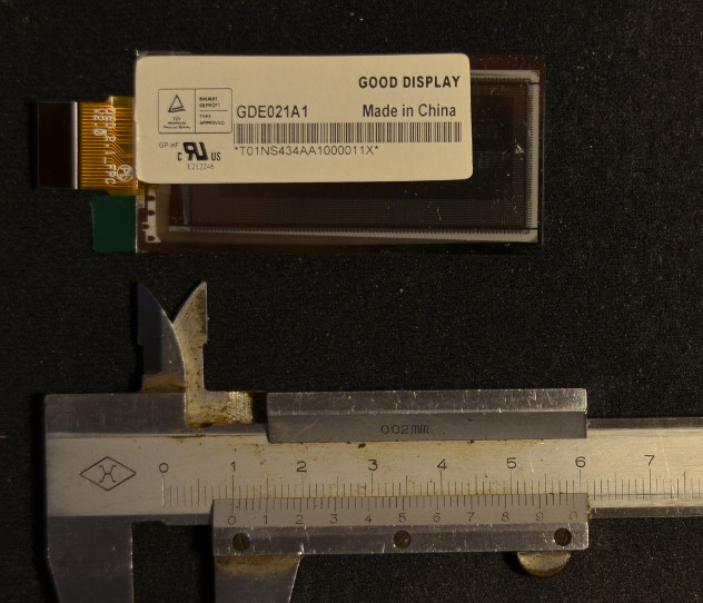 ePaper EPD display back side[/caption]
Electrophoretic displays (EPD) do not require any power to retain an image. Power is needed only when redrawing the screen. The technology is thus used in electronic paper readers such as Amazon Kindle or the Pebble smartwatch (correction: Pebble uses different display: Memory LCD).

Talking Nixie Clock
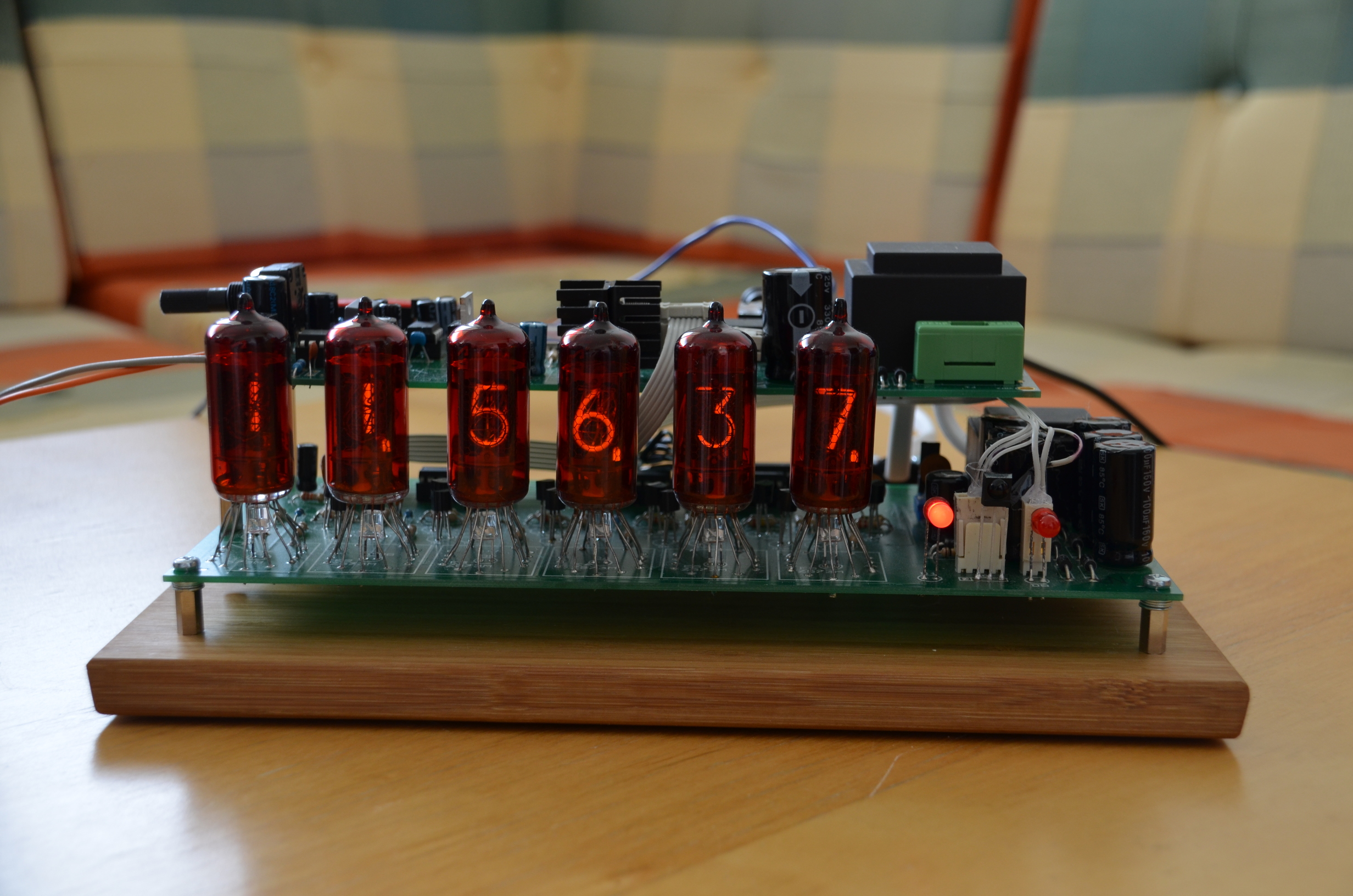
I’ve just assembled both PCB boards of my talking nixie clock together and went ‘whoa, this thing IS really beautiful!’. Check it out below, electronics porn at its best!
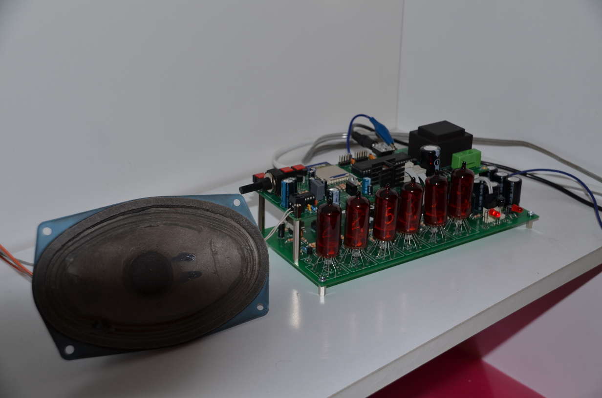
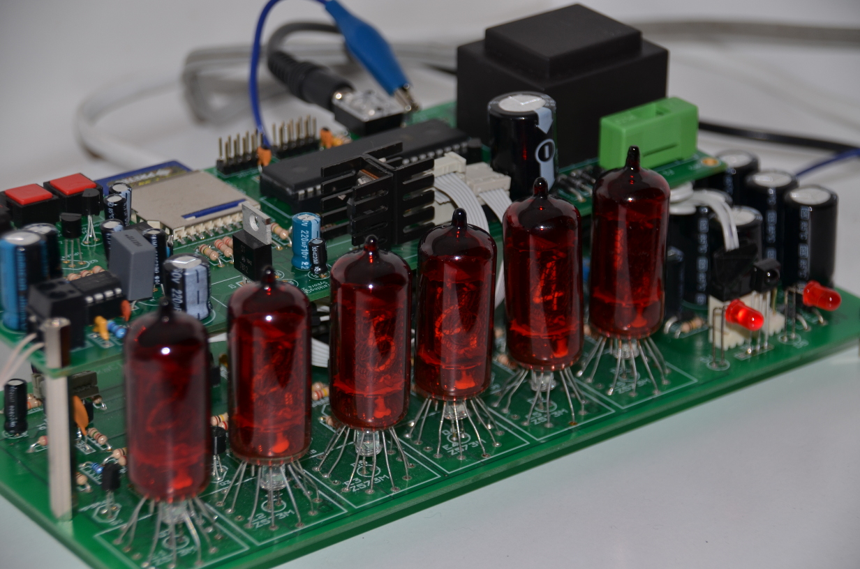

The first two pictures were taken with a flash to get good details, the last one without, hence a poorer picture quality. But you at least get the idea how those nixie puppies shine!
Later I’ll get my documentation together and create a proper project page with all schematics, pcbs, source codes, better pictures etc etc.
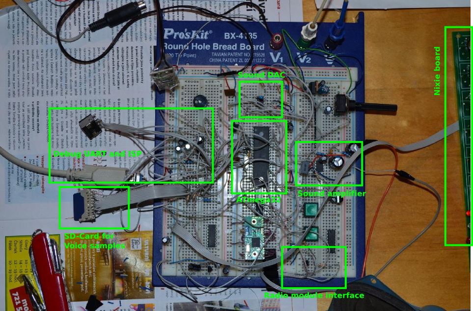
Talking Clock Prototype
I am working on a talking clock with a remote IR control. The idea is that when I awake at night I don’t have my glasses on, hence I cannot recognize digits on a clock display. So I figured out that what I need is a talking clock that could tell me the time aloud. The audible announcement is triggered by a button press on a standard infrared remote, normally used to control my hi-fi equipment.
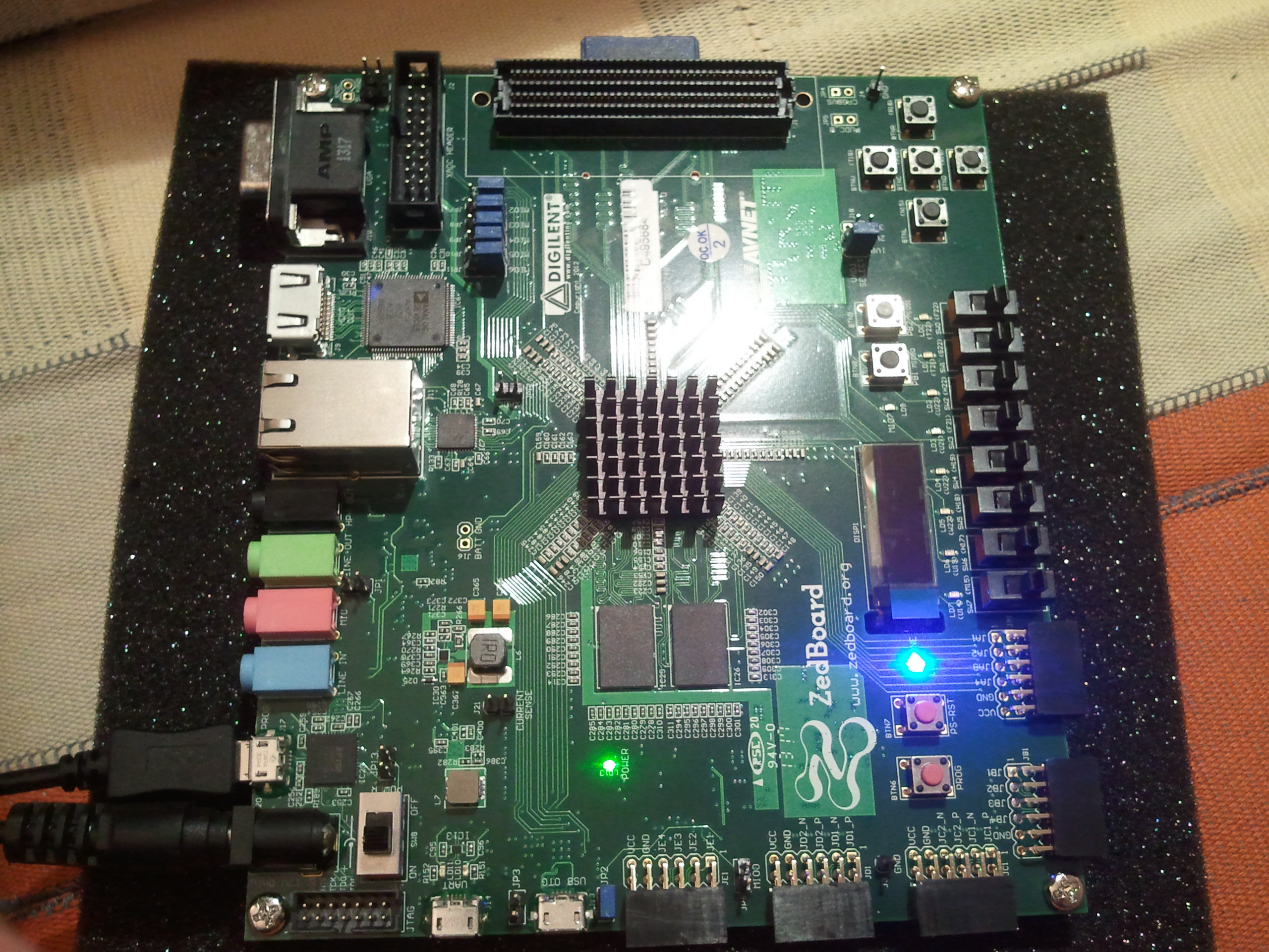
ZedBoard: Late Xmas present has arrived!
Finally, after much waiting, my ZedBoard arrived on Tuesday. See it shining in the picture above, isn’t it lovely?
So far I managed only to unbox it and turn it on… Hence only a few notes on the beginnings:
- Running Vivado 2013.3 in Fedora Linux: see my previous post.
- Running the demo Linux bitstream from the supplied SD card: you need to reconfigure switches, at least JP8, JP9 should be at 3V3 side. Best to see the README on the SD card. The default configuration (JP7-11 at GND) is for JTAG download.
- Installing USB-JTAG cable drivers in Linux: surprisingly, all I needed to do was to run Vivado/2013.3/data/xicom/cable_drivers/lin64/digilent/digilent.adept.runtime_2.14.3-x86_64/install.sh as root.
- Missing impact tool in Vivado 2013.3: impact is deprecated. Use Hardware Manager / Open Target tabs in Vivado GUI.
Xilinx Vivado 2013.3 on Fedora 18: Working around a D-Bus bug
Running Xilinx Vivado 2013.3 (webpack license) on Fedora 18 may fail with the following error message:
$ vivado

****** Vivado v2013.3 (64-bit)
  **** SW Build 329390 on Wed Oct 16 18:26:55 MDT 2013
  **** IP Build 192953 on Wed Oct 16 08:44:02 MDT 2013
    ** Copyright 1986-1999, 2001-2013 Xilinx, Inc. All Rights Reserved.

INFO: [Common 17-78] Attempting to get a license: Implementation
process 17688: arguments to dbus_move_error() were incorrect, assertion "(dest) == NULL || !dbus_error_is_set ((dest))" failed in file dbus-errors.c line 282.
This is normally a bug in some application using the D-Bus library.
  D-Bus not built with -rdynamic so unable to print a backtrace
Abnormal program termination (6)
Please check '/home/jara/hdl/hs_err_pid17688.log' for details
The workaround is to make the D-Bus communication socket file /var/run/dbus/system_bus_socket unavailable when the Xilinx tools run.
Hardware/Software Co-Simulation (PORTAL)
I devised PORTAL as a means for validating our hardware accelerator cores (ASVP in SMECY) in a co-simulated environment together with control software. The basic structure of PORTAL is shown below:
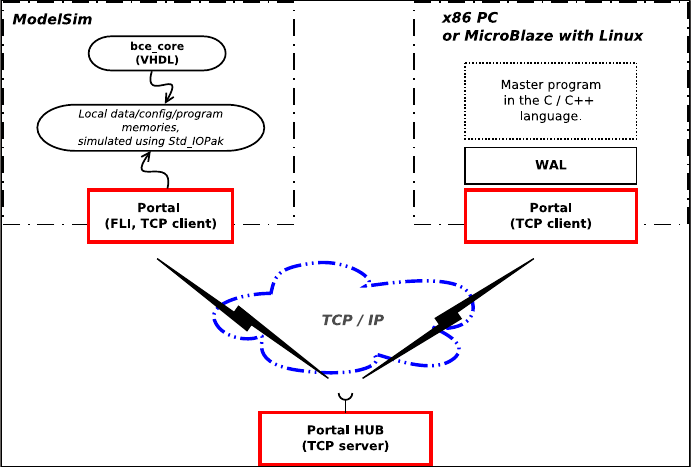
PORTAL is a a communication library that connects a hardware model simulated in ModelSim to its control software running on a PC. Communication is done over TCP/IP.
In PORTAL the primitive communication abstraction is a shared memory. All PORTAL clients have a common access to a (virtually) shared 32-bit address space. Any client can dynamically claim and register any unoccupied memory range in the address space and start to serve read/write requests generated by other clients. Management of the virtual address space is dedicated to the central sever, PHUB.
MASSTEST: Automated validation/verification testing
In 2009 I joined UTIA and started working on the Apple-CORE project. The project was already in its second year, hence there had been already plenty of implementation work done. My first assignment was to prepare a test suite of simple assembly-level programs for validation of the UTLEON3 processor. The initial approach was quite naive, though: I produced a test program, observed that it does not run as intended, and reported a bug via e-mail to my colleagues. However, it quickly turned out that bugs were so proliferated that fixing one place often broke other things… Running validation tests had to be automated, and the MASSTEST was born.