FreeRTOS tasks and queues
In my previous homebrew projects I did not use any operating system in the embedded processors. Software was programmed on a bare-metal hardware. In my Talking Clock project I created a simple cooperative event-processing abstraction layer, but it was very limited.
![image from Framebuffer Drawing with u8glib [VIDEO]](/posts/2014/2014-07-02-framebuffer-drawing-with-u8glib/images/epd_photo_axis_xy.jpg)
Framebuffer Drawing with u8glib [VIDEO]
GDE021A1 is a graphics display with a resolution 172x72 pixels, each pixel is 2 bits deep (4 shades of grey). The display has an internal controller SSD1606 with a framebuffer. The framebuffer size is 172*72*2/8=3096 Bytes. When the display is powered up, the system processor sends initialization sequence that first sets up controller’s internal registers (the controller SSD1606 is fairly generic) and then sends new framebuffer content. The display controller then autonomously pushes the framebuffer contents to the physical screen.
The display controller can be configured to orient the framebuffer almost any way. I configured it into a landscape mode, with the X-axis going right and the Y-axis down, as shown on the photo.

EPD Display Working!
Today I have managed to get the GDE021A1 ePaper display (EPD) working! I used my minimal EPD-Driver board, which implements a flat-flex cable connector and a booster circuit for the display. The booster generates high voltages needed for display operation (around +-25V). The display is driven by STM32F101 Cortex-M3 CPU, mounted on a universal PCB. The picture below depicts my workbench setup (click to see a full-size image):
[caption id=“attachment_410” align=“aligncenter” width=“1205”]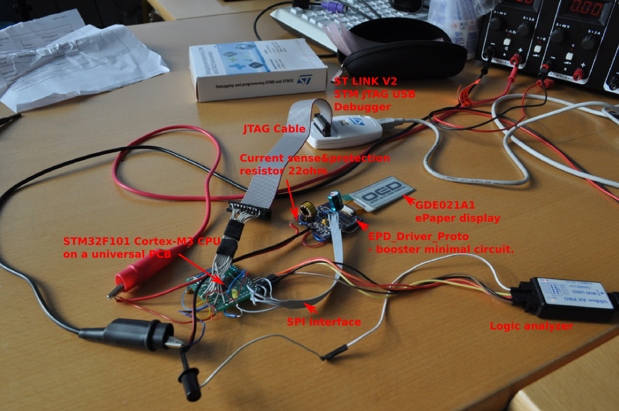 EPD Driver Prototype-workbench view with captions[/caption]

Li-On Battery Charging (and Discharging)
In my PIP-Watch project I will use a Li-On battery to provide power. Li-On batteries are easy to use in hobby projects: they are light, small, with high capacity, and they come in variety of sizes. Most (not all) Li-On batteries have nominal voltage 3.7V, hence you can directly power your standard 3.3V digital logic directly, using only a simple low-drop linear regulator (e.g. LD59015).
For my first experiments I chose Nokia BL-4C Li-On battery. It’s nominal voltage is 3.7V, charging (maximal) voltage is 4.2V, the capacity is 860mAh.
Voltcraft VC-870 Multimeter Used With UNI-T UT-D04 USB Cable
Target hardware:
Software repository location:
The issue this software solves: Although the Voltcraft multimeter and the UNI-T USB cable are hardware compatible (the USB cable adapter fits into the multimeter connector perfectly), the software requirements are different. Original Voltcraft USB cable, which costs tripple the UNI-T cable by the way, mimics RS232 adapter when plugged in USB host PC. The UNI-T cable uses different chip internally and behaves like a HID device. On the other hand, UNI-T multimeters use different communication protocol over the serial line than the VC870 does.

Fun with a switching regulator MC34063A
Being mostly ‘digital’ guy, I’ve always shied off from switching mode power supplies because they are too much analog to my liking. I decided to break my habit by playing around with MC34063A, a 1.5-A Boost/Buck/Inverting Switching Regulator.
I tried an inverting topology that generates -12V from +6V power supply. A copy of schema from datasheet is below, and an implementation on a breadboard can be seen above at the page tile:
[caption id=“attachment_372” align=“aligncenter” width=“827”]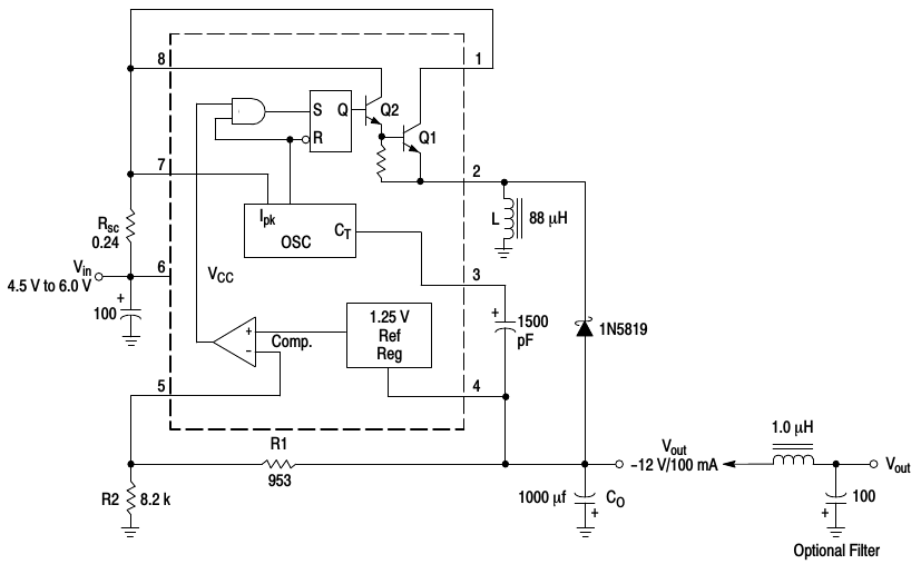 MC34063A: Inverting topology[/caption]
The converter works by first charging coil L by a current drawn through transistor Q1. When Q1 is switched off the energy stored in the coil is discharged through diode 1N5819 into output capacitor Co. Because current through the coil L goes always from top to bottom (as drawn in the schematic above), the discharging phase is effectively pulling the output voltage below ground level.
Logic Voltage Levels
Again and again I need to look up the logic voltage levels of various logic gate standards like HC, HCT, LVT, and so on. I found a nice article on EETimes: A brief recap of popular logic standards. The page has a picture that recaps all the popular standards along with their Voh, Vih, Vil, and Vol voltage levels. However, the picture resolution is very low quality, and it is also not evident at the first glance what is the relation between standards. So I redraw the picture in Inkscape, an open-source SVG editor. The result is here (click to see large image):

Bluetoothing to Android Tablet
Today I tried pairing my UART-to-Bluetooth adapter to a Nexus 7 tablet to see how it works. On the tablet I used BlueTerm, an open-source terminal emulator for communicating with any serial device using a bluetooth serial adapter.
I connected my Bluetooth adapter through a USB/UART adapter to a PC. On the PC in a terminal emulator the following sequence of commands is sent to the BT adapter:
///
at*agln="PIP-Watch",0
at*agfp="1234",0
at*addm
The three slashes are an escape sequence to put the adapter into the AT-mode. Then we set BT device name and a PIN. Finally we exit the AT-mode, entering data mode. The adapter now awaits BT connections.
Foolish Attempt at Soldering an FPC Connector with 0.5mm Pitch, and a Prototyping PCB Design
Mechanical drawing of my EPD ePaper display GDE021A1 is shown below. Signals to the display are connected via a 24-pin flex flat cable. The pitch between pins is only 0.5mm. A suitable matching connector is MOLEX 52435-2471 FPC RCPT 24PIN 1ROW.
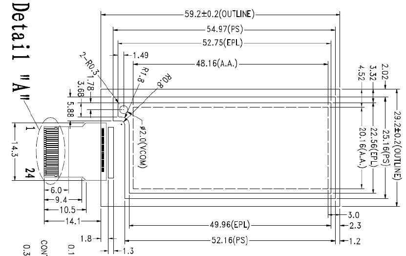
On Thursday I tried soldering thin wires directly on the MOLEX connector I got from Farnell. However, my attempt was very naïve because the pitch between pins on the connector is only 0.5mm. So I failed.
New Project: PIP-Watch
I started a new project called PIP-Watch: Personal Information Panel/Watch. It will be a kind of smartwatch. It will use an ePaper display and a bluetooth connection to a smart-phone.
I also registered the project on hackaday.io, to take part in this year’s Hackaday Prize, which will send one hacker into space!