Practical AI in HW Development: Importing BGA Pad-to-Die Lengths from Excel to Kicad Footprint
In hardware design, tedious manual data entry is a common bottleneck. I recently explored how the ‘AI revolution’ - specifically LLMs and GitHub Copilot - could automate a specific, repetitive task: importing BGA pad-to-die lengths into KiCad 9. The input Excel table, downloaded from Altera site, has around 270 rows, so the motivation to not do the import by manually entering numbers into software was pretty high.
What is the Pad-to-Die Length
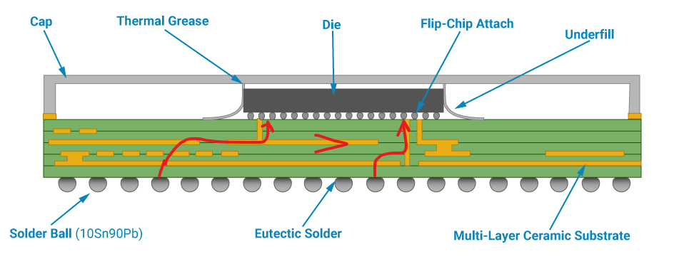
The picture bellow shows a cross section of a typical integrated chip in a BGA package. Balls at the bottom are soldered to the PCB, while the actual IC silicon die is much smaller and sits on a ceramic substrate. The substrate acts as an intermediary routing layer, connecting the silicon die to the BGA balls. The traces between balls to the die are not the same length. The pad-to-die length, or package length, is the length of the internal trace in the package; it is different for every pad or ball (unless the IC designer takes care to do the package delay matching).
Why is Pad-to-Die Length Important
Most of the time the pad-to-die length is not important. The difference in length in the internal traces is just few millimeters and this is not typically significant at all.
But there are cases where few millimeters are a lot: for example in the DDR DRAM routing the PCB layout engineer must equalize trace lengths on the PCB so that all parallel signals arrive to the DRAM at the same time. The total length equalization is done at sub-millimeter precision, therefore it must take into account the difference of length in the BGA package and compensate for it.
In case of the LPDDR4 interface in Altera Agilex 3 FPGA the manufacturer defines the design rules that the PCB layout must follow:

The package lengths must be included in the length matching. Altera provides an excel sheet that shows the per-pin values for about 270 balls of the device (the complete BGA has 896 balls):

How is Pad-to-Die Length Handled in Kicad PCB Editor
In Kicad 9 footprint editor there is an option to specify the pad-to-die length for a pad:

How the AI Helped with Importing the Lengths to Kicad
Kicad is open-source and the footprint data file is text-readable and well document. There even exist ready-made libraries in python that directly work with the file format. Likewise, excel table is easy to read in python or could be converted to CSV at the worst.
I asked Claude Sonnet 4.5 how could I access Kicad data (schematic, PCB, footprints) from python scripts and Claude gave some code examples. Then I mentioned specifically that I need to import pad to die length from excel, and Claude generated a script for me that does just that:

I downloaded the generated script, inspected the python code and it looked reasonable. So I ran it over the existing BGA footprint with the excel table from Altera.
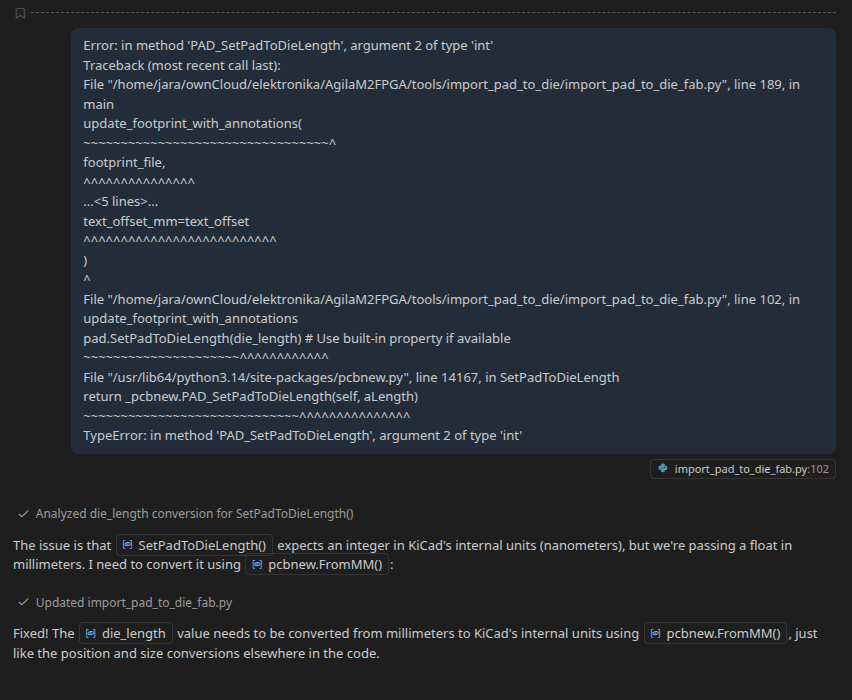
The script ran… and immediately crashed with a pythonic error exception. Things were not quite perfect. Undeterred, I opened the script in vscode with Github Copilot enabled, and copied into the prompt the error message from python, as shown in the first line in the picture below. This is where the workflow shifted from generation to iterative debugging with Copilot.

In agentic mode Copilot LLM thinks longer and can autonomously make multiple changes in the source code to satisfy a request.
The error message says that a library method SetProperty() takes different arguments than were given:
pad.SetProperty("pad_to_die_length", f"{die_length:.3f}mm")
Here, unfortunately, Copilot did not understand the intent of the script. Instead of fixing the call site or finding a better method, it decided to remove the SetProperty() call altogether. This is quite wrong decision, since this call of SetProperty() is central to the script: it sets the pad-to-die length in the footprint, which is exactly what we want to achieve.
Not comfortable with Copilot yet, I turned to traditional documentation, searched the internet the old way and found the replacement function called SetPadToDieLength(). I changed the code to use it.
However, my correction was not quite right and so I got another python exception about wrong argument type. I copied it into the prompt, and now the Copilot machinery worked correctly a changed the code to add a call to FromMM() function in the argument of SetPadToDieLength():
This fixed the PadToDie code, but it was not the end of journey for the small script. There were additional problems with saving the footprint back to a file, which took multiple iterations with Copilot to resolve. At one point the file saved by the script was not a footprint, but a dummy PCB containing the footprint. I provided the helpful hint to Copilot that “the save file is a pcb, not a footprint!” and this triggered another wave of changes and fixes, which was kind of fun to watch. But in the end the script worked and provided a footprint file with pad-to-die lengths included.
Conclusions
I think the practical problems were caused by uncertainty in the version of Kicad libraries that I had installed. Both Claude and Copilot did not know which version I had (but they did not ask) so they generated some ‘common’, most probable code which roughly worked but was broken in critical places.
It is an open question how much of ‘coding knowledge’ one must have to efficiently use AI coding agents. Had I not caught the very first miss-step of Copilot, where it purportedly ‘fixed’ the script but made it useless, it could not finish the task. On the other hand, the generated code saved me a lot of time I would spent studying Kicad file formats and API. The AI code-gen works as force multiplier for those who already know the basics. As usual, perilous to us all are the devices of an art deeper than we possess ourselves.
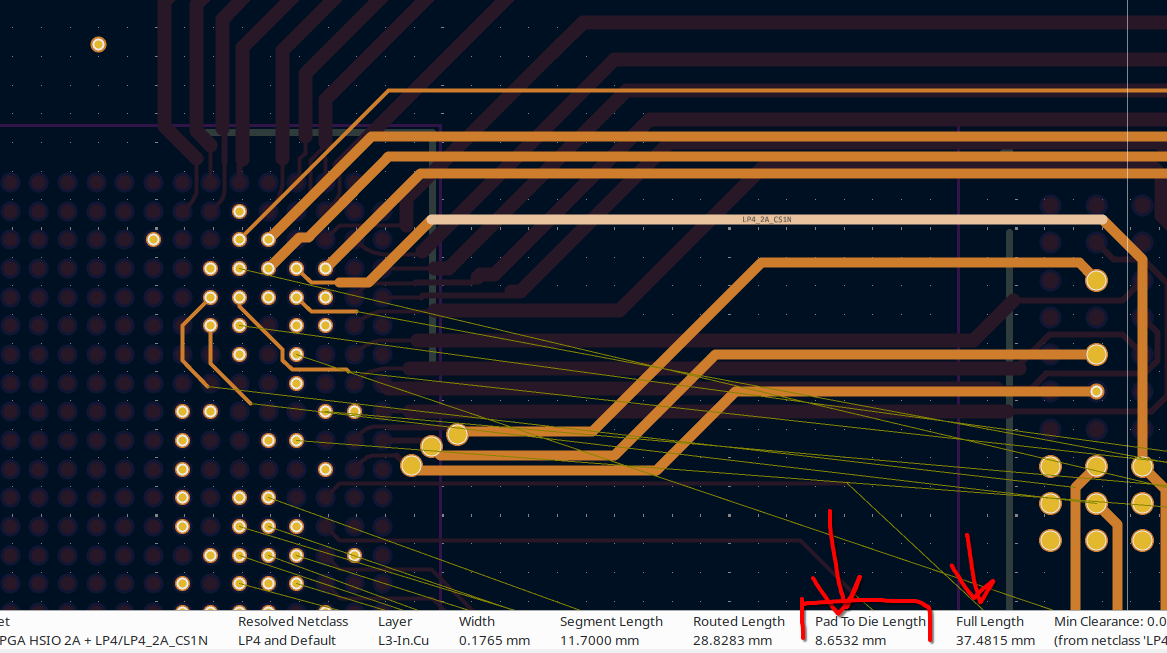
The picture below shows the achieved result: Routing in Kicad, when you select a trace the pad-to-die length is shown at the bottom of the screen, along with routed trace length and the full length: