Below you will find pages that utilize the taxonomy term “Hackaday_2014”
Posts
read more
Bluetooth Power Modes
In previous post we discussed CPU power consumption in PIP-Watch. Today we look into Bluetooth power consumption because it is significant as much as the CPU power.
Posts
read more
Processor Low-power Optimizations in PIP-Watch
Processor Power
The PIP-Watch is a battery-powered device that will be continuously on, hence the average power consumption is one of the most important engineering aspects.
In this post I will go through two simple steps of optimizing CPU power - sleep modes and lowering the clock frequency. In a next separate post we will look into Bluetooth module power.
Posts
read more
PIP-Watch Boards & Assembly
The printed circuit boards for PIP-Watch Zero came from Pragoboard fab on Friday 12 Sept. I ordered three pieces because the cost is practically identical as for two or one.
[caption id=“attachment_484” align=“aligncenter” width=“845”]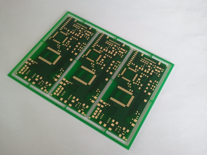 PIP-Watch Zero: Pristine PCBs from fab[/caption]
On Saturday I assembled one board, and on Sunday I tested it and started working on firmware. I had some problems with PLL in the microcontroller - the CPU hard-resetted the instant the PLL was enabled. Eventually I found a bad solder joint on one of the CPU’s power supply pins.
Posts
read more
PIP-Watch "Zero" - Schematic, BOM, and Layout
Schematic [PDF], BOM, and PCB layout for my PIP-Watch “Zero” was completed during this week. Layout data was sent to a local PCB fab - pragoboard.cz. The board should be ready and shipped during the next week.
The PCB is is 80mm*35mm. The top side is dedicated to the EPD display, battery (underneath the display), 3 push-buttons and 4 LEDs. The bottom side carries all the main electronics - processor, bluetooth modem, display driver, and power source.
Posts
read more
FreeRTOS tasks and queues
In my previous homebrew projects I did not use any operating system in the embedded processors. Software was programmed on a bare-metal hardware. In my Talking Clock project I created a simple cooperative event-processing abstraction layer, but it was very limited.
Posts
read more
Framebuffer Drawing with u8glib [VIDEO]
GDE021A1 is a graphics display with a resolution 172x72 pixels, each pixel is 2 bits deep (4 shades of grey). The display has an internal controller SSD1606 with a framebuffer. The framebuffer size is 172*72*2/8=3096 Bytes. When the display is powered up, the system processor sends initialization sequence that first sets up controller’s internal registers (the controller SSD1606 is fairly generic) and then sends new framebuffer content. The display controller then autonomously pushes the framebuffer contents to the physical screen.
The display controller can be configured to orient the framebuffer almost any way. I configured it into a landscape mode, with the X-axis going right and the Y-axis down, as shown on the photo.
Posts
read more
EPD Display Working!
Today I have managed to get the GDE021A1 ePaper display (EPD) working! I used my minimal EPD-Driver board, which implements a flat-flex cable connector and a booster circuit for the display. The booster generates high voltages needed for display operation (around +-25V). The display is driven by STM32F101 Cortex-M3 CPU, mounted on a universal PCB. The picture below depicts my workbench setup (click to see a full-size image):
[caption id=“attachment_410” align=“aligncenter” width=“1205”]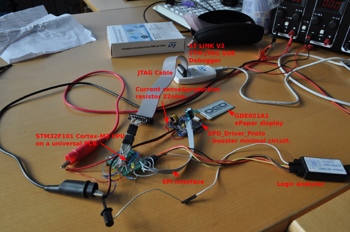 EPD Driver Prototype-workbench view with captions[/caption]
Posts
read more
Li-On Battery Charging (and Discharging)
In my PIP-Watch project I will use a Li-On battery to provide power. Li-On batteries are easy to use in hobby projects: they are light, small, with high capacity, and they come in variety of sizes. Most (not all) Li-On batteries have nominal voltage 3.7V, hence you can directly power your standard 3.3V digital logic directly, using only a simple low-drop linear regulator (e.g. LD59015).
For my first experiments I chose Nokia BL-4C Li-On battery. It’s nominal voltage is 3.7V, charging (maximal) voltage is 4.2V, the capacity is 860mAh.
Posts
read more
Bluetoothing to Android Tablet
Today I tried pairing my UART-to-Bluetooth adapter to a Nexus 7 tablet to see how it works. On the tablet I used BlueTerm, an open-source terminal emulator for communicating with any serial device using a bluetooth serial adapter.
I connected my Bluetooth adapter through a USB/UART adapter to a PC. On the PC in a terminal emulator the following sequence of commands is sent to the BT adapter:
///
at*agln="PIP-Watch",0
at*agfp="1234",0
at*addm
The three slashes are an escape sequence to put the adapter into the AT-mode. Then we set BT device name and a PIN. Finally we exit the AT-mode, entering data mode. The adapter now awaits BT connections.
Posts
read more
Foolish Attempt at Soldering an FPC Connector with 0.5mm Pitch, and a Prototyping PCB Design
Mechanical drawing of my EPD ePaper display GDE021A1 is shown below. Signals to the display are connected via a 24-pin flex flat cable. The pitch between pins is only 0.5mm. A suitable matching connector is MOLEX 52435-2471 FPC RCPT 24PIN 1ROW.
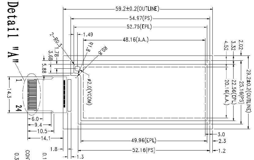
On Thursday I tried soldering thin wires directly on the MOLEX connector I got from Farnell. However, my attempt was very naïve because the pitch between pins on the connector is only 0.5mm. So I failed.
Posts
read more
New Project: PIP-Watch
I started a new project called PIP-Watch: Personal Information Panel/Watch. It will be a kind of smartwatch. It will use an ePaper display and a bluetooth connection to a smart-phone.
I also registered the project on hackaday.io, to take part in this year’s Hackaday Prize, which will send one hacker into space!
Posts
read more
Bluetooth Module (Re-)Investigation
Some five years ago I bought a nice UART-over-Bluetooth adapter module. The module emulates a serial port (UART) over a Bluetooth connection. All necessary chips and an antenna are mounted on a small PCB board depicted below.
The type I’ve got is the cB-OEMSPA310i-04 with an internal antenna. The module requires only a 3.3V power.
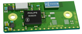
Communication with the module is over serial UART at 3.3V logic levels. The basic RXD/TXD signal pair is complemented with hardware flow control via RTS/CTS, and an optional BT connection status via DSR/DTR. A three-colour LED (red, blue, green) can be directly connected to dedicated pins on the module to visually indicate the state of module to the user.
The BT module is controlled by standard AT commands. When powered up or after a reset the module is in a data mode with no connection over BT. Local application microcontroller connected to the RXD/TXD/RTS/CTS signals first sends an escape sequence, which normally consists of three forward slashes ‘///’. This puts the module into the AT mode. In AT mode the strings sent over the local UART are interpreted as commands, while in data mode all data is passed through to bluetooth and over the air.