I am starting a new hobby project called X65: I intend to create an open-source computer based on the “vintage” 6502 processor, which is still in production as the W65C02. The original 6502 was used in many home personal computers of the ’80s: Commodore, Atari, Apple II and so on. My computer will be called OpenX65.
Features as planned:
- use W65C02 and (optionally) W65C816 (the 16-bit version) CPU
- software compatibility with the Commander X16: a modern retro computer, developped by the 8-bit Guy
- use only parts that are in production and readily available from normal distributors such as Mouser, Farnell etc.
- no cheating by using a hidden powerful ARM processor that does some heavy lifting
- open-source design as much as possible
- low-cost as much as possible
- DIY and hobby-builders friendly
The current architecture:
- two-PCB construction: Motherboard (mo-bo) and Video-Audio board (va-bo), each board will be 100x100mm and 2-layers. This has several advantages:
- the PCBs can be placed inside Eurocard housings
- 100x100mm / 2-layers is cheaply manufactured by many PCB vendors
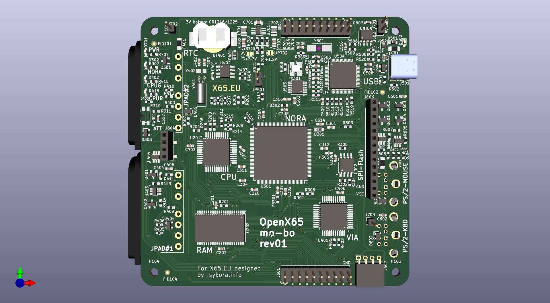
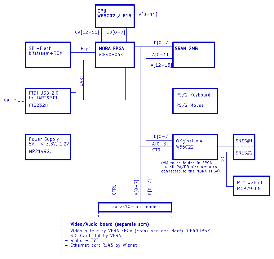
The motherboard (mo-bo) PCB will have:
- CPU: W65C02 in the QFP-44 package
- Memory: 2MB asynchronous SRAM
- Lattice FPGA iCE40HX4K (TQFP-144) to handle address decoding, glue logic, PS/2 interfaces. The FPGA design will be called “NORA” = NORth Adapter, because it works as traditional north bridge in a PC. This FPGA has a fully open-source toolchain developed by the icestorm project.
- VIA chip W65C22 (which I intend later to integrate inside of the FPGA)
- two ports for SNES controllers, connected to VIA
- two PS/2 ports for keyboard and mouse, handled by NORA / note: this will be more difficult than necessary to implement, if we want the Commander X16 compatibility, since they have an “arduino” for PS/2 🙁
- RTC chip with backup battery
- integrated debug support in the form of FTDI USB / UART+SPI chip
- power input: 5V via USB-C port
The video-audio (va-bo) PCB will have:
- video interface from the Commander X16, which is Lattice FPGA iCE40UP5K called “VERA” (Video Embedded Retro Adapter)
- VGA, S-Video and composite video output ports as in the VERA design.
- SD-card slot handled by VERA
- audio interface – currently open… the Commander X16 uses old Yamaha synthesizer YM2151, which is 20 years out of production. Since we want to be software-compatible, I think this needs be implemented in an FPGA – either add to VERA, or additional one on the VA-Bo.
- 10/100Mbps Ethernet port RJ45 realized by Wiznet W6100.
Current project state at E03/2023:
- Motherboard schematic and PCB rev01 is done; waiting for the first PCB from a fab, then I will do component assembly, and test
- Video/Audio board is not designed.