Being mostly ‘digital’ guy, I’ve always shied off from switching mode power supplies because they are too much analog to my liking. I decided to break my habit by playing around with MC34063A, a 1.5-A Boost/Buck/Inverting Switching Regulator.
I tried an inverting topology that generates -12V from +6V power supply. A copy of schema from datasheet is below, and an implementation on a breadboard can be seen above at the page tile:
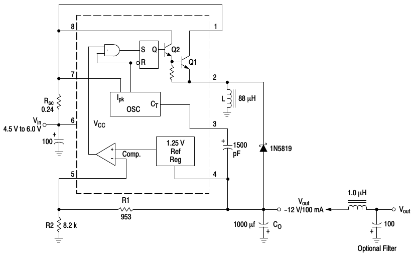
MC34063A: Inverting topology
The converter works by first charging coil L by a current drawn through transistor Q1. When Q1 is switched off the energy stored in the coil is discharged through diode 1N5819 into output capacitor Co. Because current through the coil L goes always from top to bottom (as drawn in the schematic above), the discharging phase is effectively pulling the output voltage below ground level.
Switching is controlled by an internal free-running oscillator and a comparator with a 1.25V reference. The external resistors R1, R2 set the output voltage value. The goal of the IC is to get the comparator output to zero. Because the + input of the comparator is 1.25V above pin 4, the equilibrium voltage over resistor R1 will be 1.25V, going from left to right (pin 5 to pin 4). This gives the current through R1 to be 1.25V/953ohm=1.31mA. Because pin 5 draws no current (it is comparator input), this whole current must go through R2, from ground towards R1. The voltage across the serial combination of R1 and R2 is (1.31mA * (8.2kOhm + 953Ohm))=12V. And because the current goes from left to right across the resistors, this is actually -12V with respect to ground. Hence we have calculated the output voltage because R1+R2 is parallel to the output.
Transistors Q1 and Q2 are switched by an R-S flip-flop. When output voltage of the inverter is insufficient (close towards 0V), the comparator output goes high because drop over R1 is less than 1.25V. When an oscillator outputs a high pulse the flip-flop is set, transistors open, and the coil is charged. The free-running oscillator then automatically shuts the transistors down when it goes to low level (resetting the flip-flop). This means that the duration when transistors are open is fixed, irrespective of the load.
Picture below is a photo of an oscilloscope screen, augmented with text notes. It shows the voltage on coil (IC pin 2) with respect to ground. Vertical is 4V/div, horizontal is 10us/div. The coil is ‘charged’ for 30us when the transistor Q1 is on, then discharges for 10us.
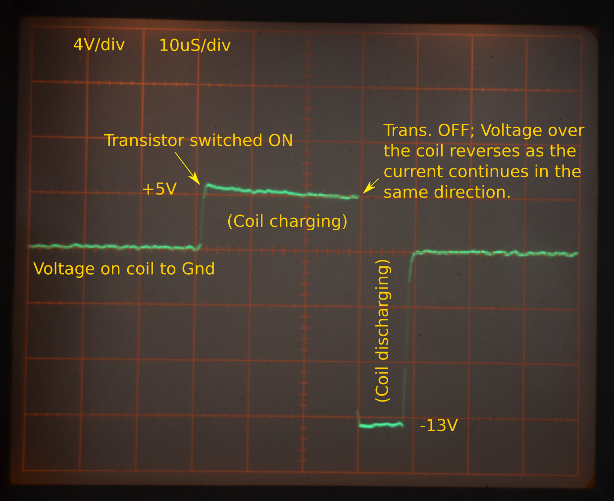
MC34063A: Coil voltage
It is tempting to point out that the coil charges for 30us with 4V and then discharges for 10us with -12V or so, giving a nice equality of voltage*time areas above and below ground, see the scope picture. However, here I hesitate because energy stored in a coil is 1/2*L*I^2. It depends on current, not voltage across the coil…
Anyway, during my experiments I overloaded the IC, letting the magic smoke out. And if you let the magic smoke out, as everybody knows, chips stop working. So much for not using a current-limited power source…